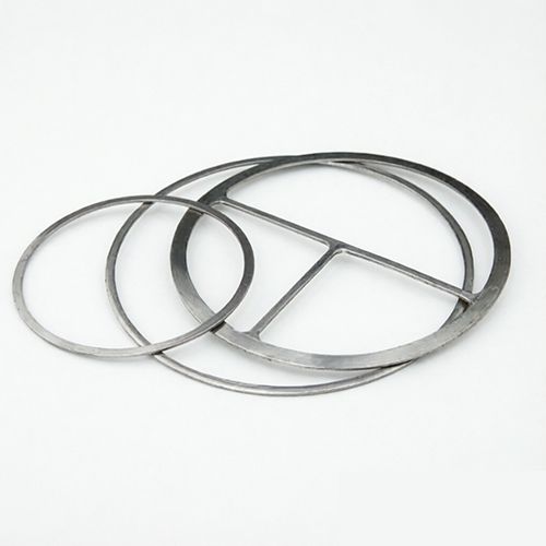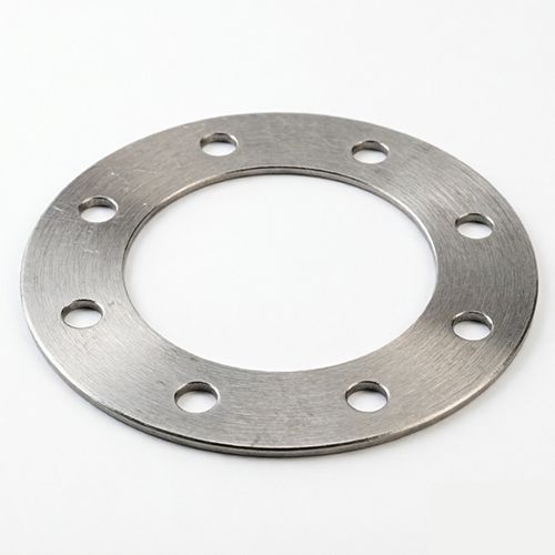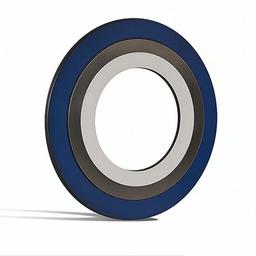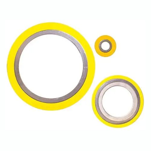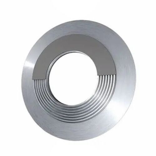

Imagine a production line down at 3 a.m. because a flange joint starts leaking steam. The maintenance team replaces the gasket, but two weeks later the same failure returns. The root cause is rarely the gasket itself—it is almost always the selection process. How to select the right corrugated metal gasket for flange connections? This question decides whether flanges seal reliably under pressure, temperature swings, and aggressive chemicals. For purchasing professionals, a corrugated metal gasket is not a commodity item. Its metal core geometry, filler material, and dimensional accuracy must match the flange standard and the operating envelope. Choosing correctly reduces downtime, leakage, and hidden supply chain costs. Ningbo Kaxite Sealing Materials Co., Ltd. has helped buyers in petrochemical, power, and chemical industries solve this exact challenge with production-ready guidance and reliable gasket supply for demanding flange connections.
Article Outline
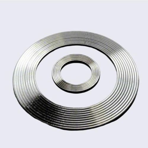
A common pain point for buyers is ordering a corrugated metal gasket only by pipe size and pressure class. When the system experiences thermal cycling or pressure spikes, the gasket loses compression and the flange starts to weep. The solution is to collect the full operating envelope before requesting a quote: flange standard, pressure class, operating temperature range, media type, and whether thermal shock or vibration is present. These inputs determine the metal core alloys, filler materials, and corrugation profiles that can actually survive the service.
| Operating Factor | What to Check | Recommended Corrugated Gasket Type |
|---|---|---|
| -196°C to 260°C with thermal cycling | Cryogenic or repeated temperature swings | 316L stainless steel core with flexible graphite filler |
| 260°C to 600°C | Oxidation, creep, and relaxation | 321 or 304 stainless steel core with graphite filler |
| 600°C to 1000°C | High-temperature relaxation and oxidation | Inconel or 316Ti core with mica/graphite filler |
| Pressure above 40 bar | Blowout resistance and bolt stress | Metallic reinforced corrugated core with calibrated compression |
Another common failure is selecting a standard 304 stainless steel corrugated metal gasket for acidic or chloride-containing media. Within weeks the metal core corrodes, the filler degrades, and the flange leaks. The solution is to map the process media to the correct core and filler combination. Corrugated Metal Gaskets usually combine a rigid metal core with a conformable filler such as graphite, PTFE, or mica. The core resists structural blowout while the filler fills flange imperfections and creates the tight seal.
| Media Type | Corrugated Core Material | Filler Material | Typical Application |
|---|---|---|---|
| Steam, hot oil, heat transfer fluids | 304 or 316 stainless steel | Flexible graphite | Heat exchangers, pipe flanges, boilers |
| Strong acids such as H₂SO₄ or HCl | 316L or Alloy 20 | PTFE | Chemical processing, acid lines |
| Oxidizing media at high temperature | 321 stainless steel or Inconel | Graphite or mica | Reactors, catalyst lines |
| Food-grade or pharmaceutical media | 316L stainless steel | Food-grade PTFE | Beverage, dairy, pharma |
A frequent field complaint is that a corrugated metal gasket feels hard, requires excessive bolt torque, and still leaks. In other cases, the gasket bottoms out and loses recovery after only one thermal cycle. The pain point is ignoring the gasket’s compression and recovery data. The solution is to check the corrugation pitch, depth, compression rate, and recovery rate against the flange stiffness and available bolt load. A well-designed corrugated metal gasket should compress enough to fill surface irregularities while retaining enough stored energy to maintain seal stress during operation.
| Gasket Parameter | Ideal Range | Risk If Out of Range |
|---|---|---|
| Compression rate | 15% – 30% | Leak path or flange damage |
| Recovery rate | ≥ 15% | Cannot absorb thermal cycles |
| Corrugation pitch | 2.0 – 4.5 mm | Insufficient contact stress or excessive stiffness |
| Thickness tolerance | ±0.1 mm | Uneven bolt load and localized leakage |
Many urgent procurement requests fail because the supplied gasket is just a few millimeters off. The inner diameter may protrude into the flow path, the outer diameter may not match the raised face, or the bolt holes may not align. Installation stops, production waits, and costs rise. The solution is to verify three dimensions against the flange drawing: inner diameter, outer diameter, and bolt circle diameter. For standard flanges, refer to ASME B16.5, EN 1092-1, or JIS B2220. For non-standard flanges, request an actual flange face drawing.
| Flange Standard | Gasket I.D. Check | Gasket O.D. Check | Bolt Circle Check |
|---|---|---|---|
| ASME B16.5 Class 150 | Match flange bore | Match raised face O.D. | Align all bolt holes |
| EN 1092-1 PN16 | Match flange bore | Match raised face O.D. | Align all bolt holes |
| JIS B2220 | Match flange bore | Match raised face O.D. | Align all bolt holes |
| Custom non-standard flange | Provide CAD drawing | Provide actual face dimensions | Provide bolt pattern |
Even when the gasket parameters are correct, field failures still occur because of overlooked installation factors. A common pain point is buying an excellent gasket but reusing it after maintenance, ignoring flange surface roughness, or applying uneven bolt torque. The seal then fails immediately or shortly after startup. The solution is to enforce basic installation rules: replace the corrugated metal gasket every time the flange is opened, verify flange surface roughness between Ra 3.2 and 6.3 µm, and tighten bolts in a diagonal sequence in three stages.
| Common Mistake | Consequence | Correct Practice |
|---|---|---|
| Reusing an old corrugated metal gasket | Compression set, leak path, blowout | Always install a new gasket |
| Ignoring flange surface roughness | Poor sealing, localized stress loss | Verify Ra 3.2 – 6.3 µm |
| Wrong bolt tightening sequence | Uneven compression, flange tilt | Use diagonal staged torque |
| Mixing different flange standards | Misaligned bolt holes, assembly delay | Match all standards before ordering |
Choose a corrugated metal core that retains strength above 500°C, such as 321 stainless steel, 316Ti, or Inconel, combined with graphite or mica filler. Check the gasket’s maximum service temperature and recovery rate to ensure it can handle thermal cycling without losing seal stress.
| Temperature Range | Metal Core | Filler | Maximum Service |
|---|---|---|---|
| 500 – 700°C | 321 stainless steel | Graphite | 700°C |
| 700 – 900°C | Inconel 625 | Mica/graphite | 900°C |
Start with the chemical concentration and operating temperature, then select a corrosion-resistant metal core such as 316L, Alloy 20, or Inconel. Pair it with PTFE filler for strong acids or chlorides. Avoid standard 304 stainless if the media contains halides or oxidizing acids.
| Chemical | Core | Filler | Key Check |
|---|---|---|---|
| Sulfuric acid | Alloy 20 | PTFE | Concentration and temperature |
| Hydrochloric acid | 316L | PTFE | Chloride pitting resistance |
Need help with a specific flange condition? Tell us your flange standard, medium, temperature, and pressure. Ningbo Kaxite Sealing Materials Co., Ltd. focuses on industrial sealing systems and supplies corrugated metal gaskets for flange connections across chemical, petrochemical, power, and food industries. The company helps buyers solve selection challenges through technical support, custom dimensions, and certified manufacturing. Visit https://www.metal-gaskets.com or contact [email protected] for a selection datasheet and quick quote.
References
1. Zhang, Y., Liu, M., 2019. Sealing performance of corrugated metal gaskets with graphite filler under thermal cycling. Journal of Pressure Vessel Technology, 141(3).
2. Brown, T. A., Wilson, J. R., 2018. Compression and recovery behavior of corrugated metal gaskets for raised-face flanges. International Journal of Pressure Vessels and Piping, 166(2).
3. Chen, L., Wang, H., 2020. Material selection criteria for corrugated metal gaskets in corrosive chemical service. Corrosion Engineering Science and Technology, 55(4).
4. Kumar, S., Patel, R., 2017. Effect of flange surface roughness on sealing performance of corrugated metal gaskets. Journal of Sealing Technology, 12(3).
5. Davis, M. E., Lee, J. H., 2016. Leakage analysis of corrugated metal gaskets in high-temperature flanged joints. ASME Journal of Pressure Vessel Technology, 138(5).
6. Singh, A., Robinson, P., 2021. Influence of corrugation pitch and depth on contact stress distribution in gasketed joints. Tribology International, 158(1).
7. Miller, D. R., Thompson, S. J., 2018. Comparative study of graphite and PTFE fillers in corrugated metal gaskets for chemical process flanges. Chemical Engineering Research and Design, 135(7).
8. Park, J. W., Kim, S. H., 2019. Finite element evaluation of bolt load loss in corrugated metal gasket connections under thermal cycling. Journal of Mechanical Science and Technology, 33(9).
9. Fernandez, A., Gupta, V., 2020. Standardization and dimensional verification of corrugated metal gaskets for ASME and EN flange standards. Measurement, 164(8).
10. Okafor, C. I., Lee, K. S., 2022. Failure modes and corrective actions for corrugated metal gaskets in petrochemical flanged joints. Engineering Failure Analysis, 139(4).
-